The Fascinating Mathematics of Image Rotation in Gaming
Written on
Understanding Image Rotation
Recently, I embarked on a journey into the world of video game development, where I encountered the intricacies of sprite animation. While experimenting with pixel-based (or raster) image rotations, I found myself curious about how early game developers approached this challenge.
Thanks to the internet, we can easily look back in time to discover their methods. After gathering ample information and sketching various concepts, I decided to share my findings on the mathematics of image rotation in this article. If you’re interested in the technical aspects of animation or simply enjoy mathematics, you’re in the right place. Let’s begin by discussing what the title image represents.
The Pixel Grid Explained
Most digital images we encounter today, whether on smartphones, televisions, or computer screens, are pixel-based (formally referred to as raster graphics). These images use a rectangular grid to represent objects and scenes in a manner that our brains can easily interpret, a concept known as resolution.
Each rectangular unit in this grid is called a pixel, and each pixel contains a specific color value (a mix of red, green, and blue). When we view high-resolution digital images, our eyes are unable to discern individual pixels, allowing our brains to perceive the image as a cohesive object.
For instance, while you read this article, your brain likely interprets the text as printed words, but in reality, you're observing a collection of pixels that mimic the appearance of printed text.
So, how does this relate to the title image? Significantly! The title image is a simplified representation consisting of just nine pixels arranged in a 3x3 grid. Imagine zooming in on a high-resolution image until you reach this 3x3 pixel configuration.
For your convenience, I’ll reproduce the title image again below:
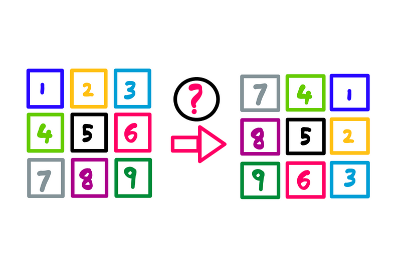
The mathematics of image rotation — Illustration created by the author
Look closely at the pixel grid shown here. Pay attention to the colors and numbers; you'll notice that the pixel grid (our simplified image) has been rotated 90° clockwise (I kept the numbers upright for clarity).
Now, let’s dive into the mathematics that makes this rotation possible. Picture yourself as a game developer from the late 80s. The algorithm I’m about to explain was widely used during that era.
However, delving into complex mathematics can be daunting. Therefore, I’ll start with a more intuitive explanation of the algorithm before we tackle the math.
The Classic Raster Rotation Algorithm
This algorithm consists of three main steps. Here’s the first step:
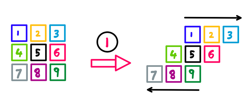
Raster rotation: Step 1 — Illustration created by the author
The process involves:
- Shifting the top row (pixels 1, 2, and 3) to the right by one pixel.
- Moving the bottom row (pixels 7, 8, and 9) to the left by one pixel.
- Keeping the center row unchanged.
Now, let’s move on to the second step:
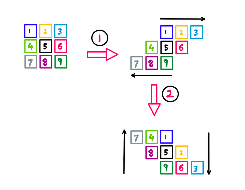
Raster rotation: Step 2— Illustration created by the author
In this step, we focus on the columns:
- The left-most column (pixel 7) moves up by two rows.
- The second-left column (pixels 4 and 8) shifts up by one row.
- The center column (pixels 1, 5, and 9) remains unchanged.
- The second-right column (pixels 2 and 6) moves down by one row.
- The right-most column (pixel 3) shifts down by two rows.
Finally, let’s examine the third step:
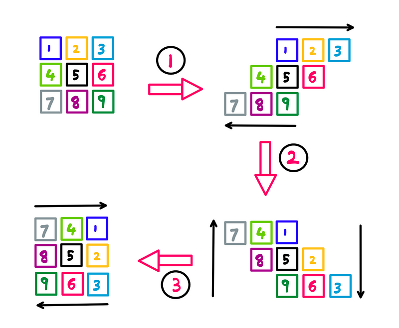
Raster rotation: Step 3— Illustration created by the author
This step mirrors the first step but applies it to the results of the second:
- Shift the top row (pixels 7, 4, and 1) to the right by one pixel.
- Move the bottom row (pixels 9, 6, and 3) to the left by one pixel.
- Keep the center row unchanged.
And just like that, we have successfully rotated the original 3x3 pixel grid image 90° clockwise. While we’ve developed a good intuitive understanding, we still need to delve into the underlying mathematics.
The Mathematical Foundations of Raster Image Rotation
To explore the math further, I’ll make a minor adjustment to our starting pixel grid. Instead of numbering each pixel, I'll assign (x, y) Cartesian coordinates to each one.
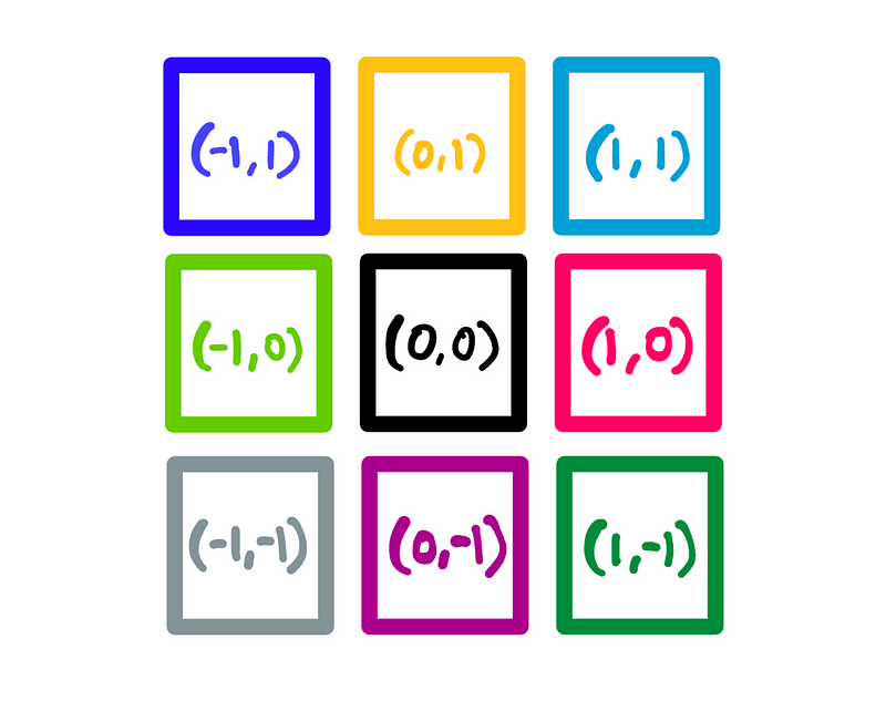
Pixel-grid with Cartesian coordinates — Illustration created by the author
In this configuration, the center pixel (black) becomes the origin (x=0, y=0). Pixels to the right have positive x-coordinates, while those above have positive y-coordinates. Negative coordinates are symmetrical, with each pixel measuring 1 unit by 1 unit.
With our mathematical model established, let’s examine the math behind step 1:
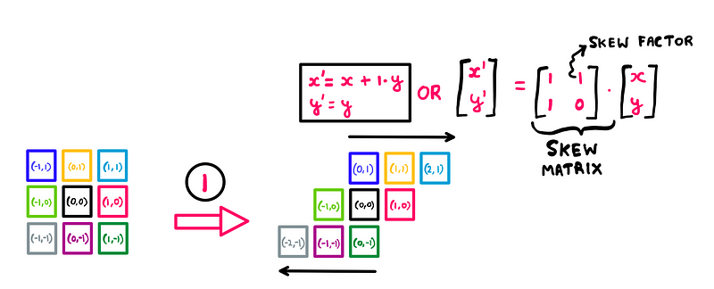
Math behind raster rotation: Step 1 — Illustration created by the author
In summary:
- Calculate a new x-coordinate for each pixel using the formula x’ = x + (1 * y).
- Retain the original y-coordinates.
Since we do not alter the y-coordinates, the movement is strictly horizontal. Pixels in the top row (y=1) are pushed to the right, while those in the bottom row (y=-1) shift left. Essentially, we are skewing the pixel grid or shearing the raster image along the x-axis.
Step 2 follows a similar reasoning:
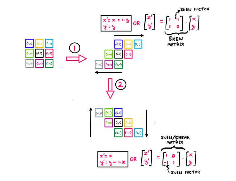
Math behind raster rotation: Step 2— Illustration created by the author
Here’s the summary:
- Keep the x-coordinates the same.
- Recalculate the y-coordinates using y’ = y - (1 * x).
As no x-coordinates are altered, the adjustments occur vertically this time, skewing in the negative direction.
Lastly, we arrive at the simplest step:
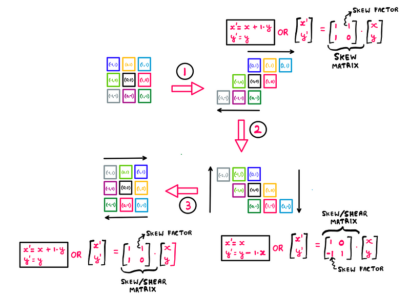
Math behind raster rotation: Step 3— Illustration created by the author
As expected, step 3 mirrors step 1 but applies it to the outcome of step 2. We shear the results from step 2 horizontally to achieve the desired rotation.
And there you have it—the mathematics underlying raster image rotation.
Transitioning from Classic Algorithms to Modern Techniques
While video game developers utilized this algorithm in the late 80s and 90s, what methods are employed today for raster image rotation?
Presently, we achieve rotation by multiplying each pixel’s coordinates using a matrix known as the rotation matrix:
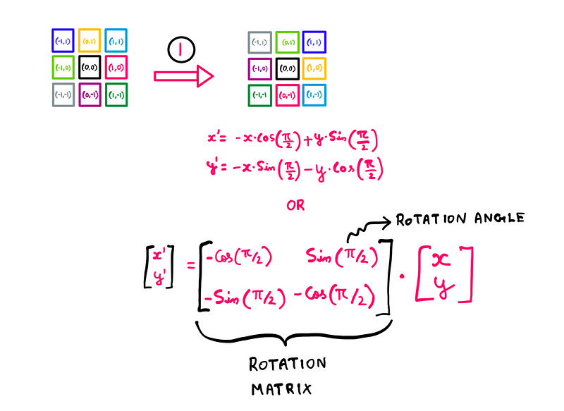
The rotation matrix — Illustration created by the author
This specific rotation matrix is part of a broader family that incorporates the principles of sine and cosine. The current matrix facilitates a 90° clockwise rotation in a single operation.
So, why didn’t game developers of the 80s and 90s use this approach? It wasn't due to a lack of intelligence; rotation matrices have been around for a long time. Instead, the limitations of computational power at that time played a significant role.
Computers back then were far less capable than those we possess today, making the computation of sine and cosine (which involves floating-point operations) quite intensive. In contrast, the old raster rotation algorithm, originally devised by Alan Paeth, was a clever workaround that relied on simple arithmetic, allowing developers to optimize performance using integer-based calculations.
In fact, the efficiency of this algorithm remains so notable that many modern image editing applications still employ it!
For those curious about the connection between shear and rotation (given our skewing process), here are the steps illustrated using shear matrices:
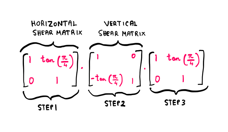
Steps 1–3 using shear matrices — Math illustrated by the author
Notice that we shear by 45° to achieve an overall rotation of 90°.
I hope you enjoyed this exploration into the fascinating mathematics of raster image rotation!
To further support my work, consider contributing on Patreon.
Reference: Alan Paeth
In this video, "How to Rotate an Image about the Origin," the speaker explains the mathematical principles involved in rotating images, providing a visual guide to the process.
The video "Rotation around a Point that is not the Origin" dives deeper into geometric transformations, detailing how to rotate images around points that are not at the origin, enhancing your understanding of image manipulation.